Chechk Autocad Drawing for Laser Cutter

Laser cutters 1 and 2
Drawings for laser cutting
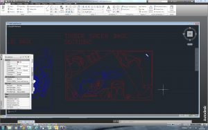
We work using AutoCAD and prefer drawings to be scaled and saved as .DWG or .DXF format.
Maximum cutting extents are 800mmx450mm. Always check material stocks with us before planning your drawings.
How to prepare your drawing file
- Scale the drawing to fit on the laser machine by reference or with a plot window from the Plot Setting dialogue box. A good way to start is to draw a 800mm x 450mm box on your drawing and design your components to fit within those constraints to avoid any parts being too big to cut.
- Explode all Blocks and join all lines into polylines to reduce the overall number lines that the computer needs to process. Typing the 'OVERKILL' command into AutoCad will help find any duplicate lines.
- Set the drawing on two layers one for cutting (Red) the other for etching (Blue) . Set a red layer 1 for cutting and a blue layer 5 for etching. A White layer can be used to for deep engraving (be aware that this can be time consuming for large areas).
- Ensure that all line weights are set at 0.05 (this can be changed in the properties menu on AutoCad)
- Before outputting your drawing from AutoCAD make sure you have done the following to a drawing before plotting. Save as a .DWG or .DXF 2010 or above file format.
- Once your drawings are at this stage you are ready to have them checked by a member of workshop staff at your allotted workshop time.
Common Issues when preparing files for Laser Cutting
Issue: The job is appearing as black lines when plotted despite the layering and line colours being correct.
Possible Cause: Line Weighting is wrong. Go to the line properties menu (right click) and change the lineweighting to 0.05)
Issue: Lines or objects cannot be changed to correct line weight or colour
Possible Cause(s):
1. The lines are grouped and must be exploded in order to select lines individually.
2. Objects are constrained. Remove constraints by typing 'DELCONSTRAINT' then apply correct line-weighting and colours to the object/lines in question.
Issue: The job preview appears blank when It has been plotted.
Possible Cause: The Job is not scaled correctly or the plot window is places incorrectly.
Issue: Nothing appears in the preview screen when plotting.
Possible Cause: Your job is scaled incorrectly and is too large or small. The selection window has been placed in the wrong area.
Scale factors for CAD software
1:1 – No Change
1:2 – 0.5
1:5 – 0.20
1:10 – 0.1
1:20 – 0.05
1:25 – 0.04
1:50 – 0.02
1:75 – 0.013333
1:100 – 0.01
1:125 – 0.008
1:200 – 0.005
1:250 – 0.004
1:500 – 0.002
1:1000 – 0.001
1:1250 – 0.0008
1:2000 – 0.0005
1:2500 – 0.0004
Applications for Laser 1 & 2
Deep engraving – Non-contact engraving & cutting – Drilling – Precision scribing – Mask production – Prototyping – Sign making – Architectural model making – Component marking – Film/overlay cutting – Textile cutting – Gasket cutting – production – Rubber stamps & seals – Membrane switches -plastics up to-12mm and MDF/Plywood cutting up to 6mm.
CorelDraw files and illustrator file formats can also be used.
Bed Size 800mm x 450mm
Materials that are not permitted or cannot be cut using the laser cutter at B.15
Packing cardboard (usually brown with internal corrugation – Fire risk
Metal – Engraving on the surface only.
Foam core board – Fire risk

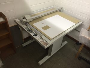
Graphtec Flat Bed Plotter
This machine allows you to cut paper and thin card (only material provided or approved for use by workshop staff!) from CAD drawings. This machine is particularly useful for net shapes that can then be folded along score lines and assembled without scorching that can occur when laser cutting.
How to Prepare your Drawing File
Drawings can be plotted from either AutoCAD or Adobe Illustrator.
When using AutoCAD:
- Ensure the drawing is correctly scaled to fit within the maximum bed size of 900mm x 600mm.
- Your drawing must be on no more than two different colour layers. One colour for cut lines and one for scoring. (Colours do not matter as long as they are different for each outcome)
- All lines must be set to have a 0.05mm line weight (properties menu, line weight)
- Explode all blocks and join all lines into polylines to reduce the overall number lines that the computer needs to process. Typing the 'OVERKILL' command will help find and remove any duplicate lines.
- Drawing must then be saved as a .DXF file before plotting.
When using Adobe Illustrator:
- Ensure the drawing is correctly scaled to fit within the maximum bed size of 900mm x 600mm.
- Your drawing must be on no more than two different colour layers. One colour for cut lines and one for scoring. (Colours do not matter as long as they are different for each outcome)
- Lines should be basic type and the stroke set to 1 pt.
- The drawing is then ready for printing from illustrator.
Once your drawing is ready consult a member of staff to begin plotting.
Maximum drawing size can be 900mmx600mm

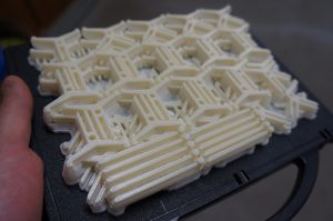
3D Printers
Be careful here! The model is only as good as your understanding of the appropriate application of this process. Misuse has become increasingly common and we urge you to think about how and way you are using this process within your work.
For more information about 3D Printing models – the different types and applications please take time to read a full guide to 3D Printing at B.15 by clicking here.
Cost is calculated using completed 3D Model File in the workshop. There are no 'overhead' costs to any type of 3D printing at B.15. Your jobs are charged at cost of the materials alone at the price they are sold to us by the manufacturer. We will thoroughly check your proposals before approving the use of any of the machines so allow time for this by getting in touch with us at the earliest convenience.
The machines work from .STL file format and your model must be a solid object not a collection of surfaces. To save the file as an.STL from your chosen modelling software you must export it and if given the option save as Binary.
After you scale the model we recommend as a general rule that you check that objects component parts are not smaller than 1.5mm thick, anything smaller will be fragile and potentially not print properly.
Modelling Software
We recommend using Rhinoceros 3D (Rhino) or Autodesk 3D Studio Max. Sketchup is a good starter programme for visualisations but can often throw up odd problems when being translated for 3D printing so we advise trying to pick up the more advanced programmes such as Rhino and 3DSmax.
Checking your files
You may want to use a free file checker on your file to indicate flaws. You may need to sign up before being able to upload files for checking and conversion to SLT format if necessary. One example is: https://makeprintable.com/
In addition to this we can further assess and repair your files using Magics Software in the workshop.
Our 3D Printers
- Stratasys F370 FDM Printer (Multiple single colour and Material options). Build Area 355mm x 254mm x 355mm High
- Projet 360 Printer. Build Area 203mm x 254mm x 203mm High
- Objet (Clear) Resin Printer.Build Area 200mm x 300mm x 150mm High

CNC Router
Operation time can vary depending on the complexity and type of CAD file used. Please consult us with your ideas before going too far into the process of modelling for this method of manufacture.
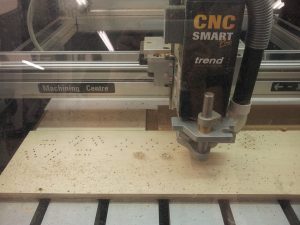
Models produced can be either profile line drawings saved as .DXF or as relief models saved as a .3DS file.
Specification Details for reference
Work piece size: 900mm x 840mm x 49mm
Standard Cutting routers are 3mm Ball Nose, 3mm Slot Cutter, 6mm Ball Nose and 6mm Slot Cutter. 45 Degree cuts can be achieved with a 'V' Bit cutting tool.
Materials
Wood, Foam, Acrylic, Ureol Chemi Wood
Software compatibility/file type:
.dxf(2D), .3ds(3D), Artcam, .stl
There is no time charge for using our CNC.
Other Equipment
Vac forming machine
Bed size of 400mm x 210mm
tschidaglearand1973.blogspot.com
Source: http://b15.humanities.manchester.ac.uk/?page_id=41
0 Response to "Chechk Autocad Drawing for Laser Cutter"
Post a Comment